
Procedure for Installation of Vertical Grinding Mill
Procedure for Installation of Vertical Grinding Mill
Proper installation is paramount to the performance, longevity, and safety of any vertical grinding mill. A meticulous approach ensures optimal operation from day one. This guide outlines the general procedure for installing a vertical grinding mill, a critical piece of equipment in modern mineral processing and powder production.
Phase 1: Pre-Installation Planning and Foundation Preparation
Before any physical work begins, a comprehensive review of all factory-supplied drawings and manuals is essential. Verify all foundation drawings against the actual site conditions. The foundation must be designed to withstand the dynamic loads and vibrations of the operating mill. It should be made of high-grade reinforced concrete and allowed to cure completely, typically for a minimum of 28 days, to achieve its full design strength.
Simultaneously, upon arrival, conduct a thorough inspection of all mill components. Check for any damage incurred during shipping and verify that all parts, including bolts, auxiliary drives, and electrical components, are present as per the packing list.
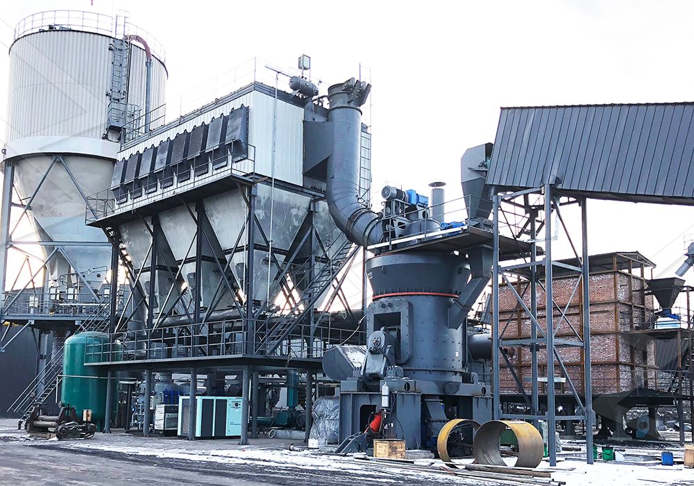
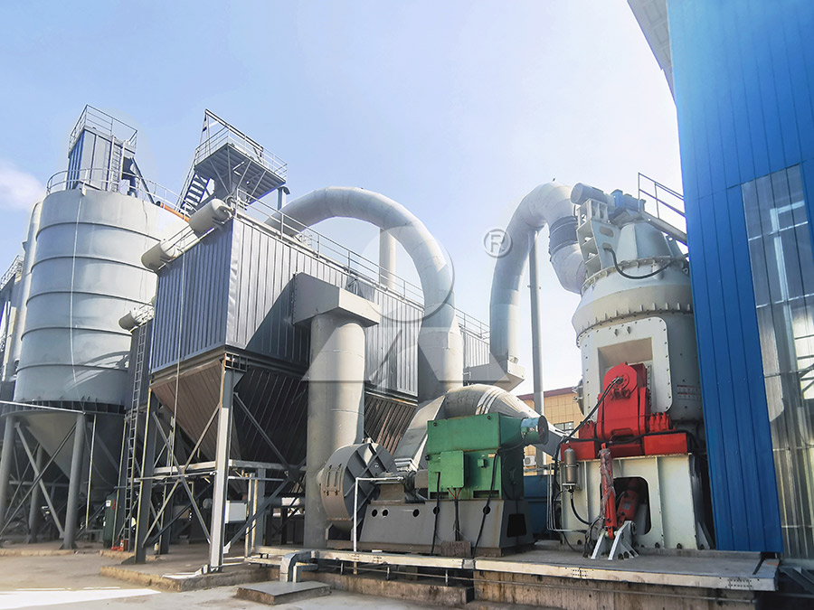
Phase 2: Main Machinery Installation
The installation sequence typically proceeds from the bottom up. Begin by positioning the base frame or bedplate onto the foundation. Use high-precision leveling instruments to ensure it is perfectly level and aligned. This step is critical, as any misalignment here will be magnified throughout the entire structure. Once aligned, proceed with the secondary grouting to firmly secure the baseplate to the foundation.
Next, carefully hoist and mount the main classification separator housing and the mill body (housing) onto the base. Ensure all connecting flanges are clean and properly aligned. Install the grinding table (turntable) onto the thrust bearing assembly. Then, install the grinding roller assemblies. These are heavy components; use appropriate lifting gear and follow all safety protocols.
For operations requiring ultra-fine powder, we highly recommend considering our MW Ultrafine Grinding Mill. With an input size of 0-20 mm and a capacity range of 0.5-25 tph, it’s engineered for customers who need to make ultra-fine powder up to 2500 meshes. Its unique design, featuring no rolling bearings or screws in the grinding chamber, eliminates common failure points and allows for external lubrication without shutdown, enabling continuous 24/7 production. It’s an ideal choice for materials like limestone, calcite, and talc.

Phase 3: Auxiliary System Integration
A vertical mill is a system, not just a single machine. Install the main reducer and motor, ensuring perfect alignment between the motor, reducer, and the grinding table shaft. Misalignment is a primary cause of premature bearing failure and vibration issues.
Connect the feeding system, which includes the rotary feeder or screw conveyor. Install the high-efficiency pulse jet baghouse dust collector and the air blower, connecting all air ducts with airtight seals. For projects demanding the highest efficiency and precision in a vertical configuration, our LUM Ultrafine Vertical Grinding Mill is a superior option. It integrates the latest grinding roller and powder separating technology, offering exceptional energy savings of 30%-50% and features a reversible structure that makes maintenance tasks like roller checking and replacement significantly easier and faster.
Finally, integrate the electrical control cabinet and run all necessary power and control cabling, ensuring all connections are tight and properly insulated.
Phase 4: Alignment, Check, and Pre-Startup
After all components are mechanically installed, perform a final overall alignment check. Verify the clearances between the grinding rollers and the grinding table as specified in the manual. This is often done using lead wires or feeler gauges.
Lubricate all bearings and gearboxes with the recommended grade of oil or grease. Conduct a thorough check of all electrical connections. Manually rotate the main motor (bump test) to ensure there is no obstruction and that the system rotates freely.
Phase 5: Commissioning and Operation
Start the system step-by-step, first initiating the dust collection and lubrication systems. Then, start the main motor without material (empty load test). Monitor amperage, vibration, and temperature of bearings closely. Once the empty load test is successful, begin feeding material slowly, gradually increasing to the designed capacity while continously monitoring all operational parameters.
Following this structured installation procedure will help garanty a smooth startup and lay the foundation for reliable, high-yielding operation for years to come. Always prioritize safety and refer to the specific manufacturer’s instructions for your equipment.