
MTM Series Trapezium Mill Installation Guide and Setup Plan
We provide a wide range of mills — including Raymond mill, trapezoidal mill, vertical mill, ultrafine mill, and ball mill, obtained ISO9001 international quality certification, EU CE certification, and Customs Union CU-TR certification. Suitable for processing minerals such as limestone, phosphate, quicklime, kaolin, talc, barite, bentonite, calcium carbonate, dolomite, coal, gypsum, clay, carbon black, slag, cement raw materials, cement clinker, and more.
The discharge range of these mills can be adjusted to meet specific processing needs, typically from 80-400 mesh, 600-3250 mesh, and can achieve the finest particle size of up to 6000 mesh(D50).
If you are looking for a reliable grinding solution to turn stone or minerals into fine powder, please feel free to contact our online customer service.
MTM Series Trapezium Mill Installation Guide and Setup Plan
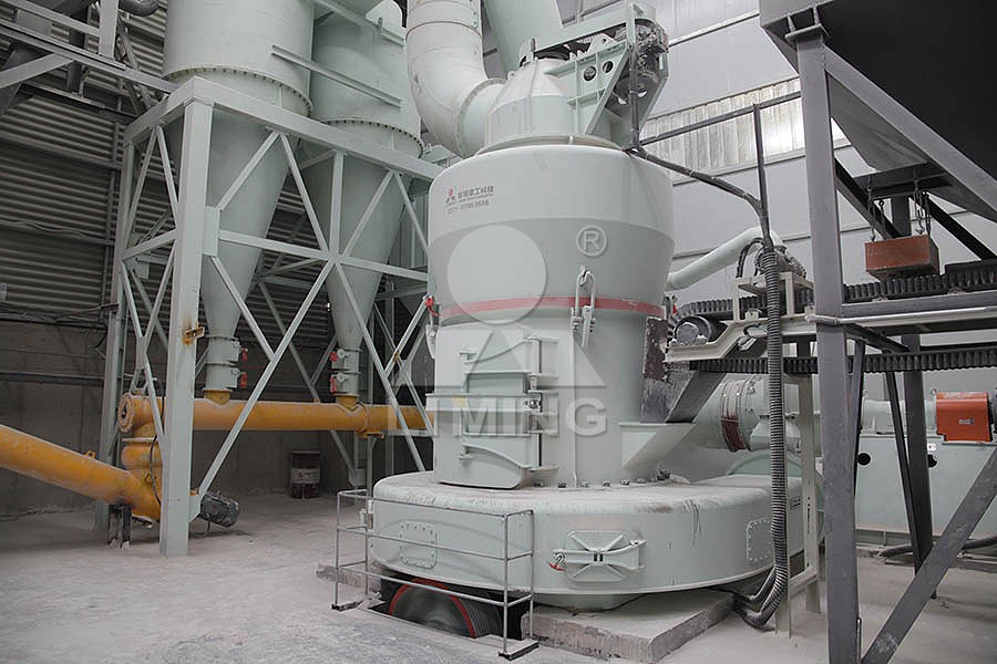
Welcome to the comprehensive installation and setup guide for the MTM Series Trapezium Mill. This document is designed to provide field engineers, project managers, and maintenance personnel with a clear, step-by-step roadmap for a successful and efficient commissioning of your new grinding system. A proper installation is the cornerstone of achieving the mill’s renowned performance, longevity, and operational efficiency. Let’s walk through the critical phases.
Phase 1: Pre-Installation Planning and Foundation Preparation
Before the equipment arrives on site, meticulous planning is essential. Begin by thoroughly reviewing the foundation drawings supplied with your MTM mill. The foundation must be designed to withstand not only the static weight of the entire mill system (including the main unit, separator, cyclone, and blower) but also the dynamic loads during operation. It should be made of high-strength reinforced concrete and allowed to cure completely—typically for at least 28 days—to achieve its full design strength.
Ensure the foundation’s anchor bolt holes are accurately positioned according to the layout diagram. The top surface of the foundation must be level; we recommend using a precision level to confirm flatness across the entire mounting area. Any deviation can lead to misalignment, causing excessive vibration and premature wear. Concurrently, verify that all necessary utilities—stable power supply, compressed air lines for the pulse dust collector, and planned routes for material feed and product discharge—are accessible at the designated locations.
Phase 2: Unloading, Handling, and Initial Placement
Upon delivery, carefully inspect all crates for signs of transport damage before signing off. Use appropriate lifting equipment with adequate capacity—always lift from the designated lifting lugs or points indicated in the manual. Never lift the main mill body using ropes or chains around the motor shaft or classifier housing. Place the main mill unit, separator, cyclone collector, and blower onto their respective foundation positions, leaving the anchor bolts loose at this stage to allow for final alignment adjustments. Position the pulse jet dust collector, ensuring its hopper and discharge valve have sufficient clearance.
Phase 3: Mechanical Alignment and Assembly
This is the most critical technical phase. Start with the main mill’s base. Using precision dial indicators and laser alignment tools, level the mill’s base frame both longitudinally and transversely. Once level, tighten the anchor bolts evenly in a cross pattern. Next, align the drive motor and reducer with the mill’s main shaft. The coupling alignment must be within the specified tolerances (typically within 0.05mm) to prevent vibration and bearing failure.
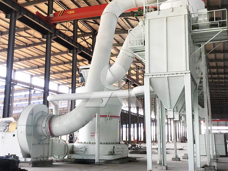
Connect the air ducting between the mill outlet, cyclone, blower, and dust collector. All connections should be airtight; use high-temperature silicone sealant on flanges. Install the screw conveyor or rotary valve under the cyclone and dust collector hoppers. Assemble the feeding system (vibrating feeder, crusher if applicable) and connect it to the mill’s inlet. Finally, fill the reducer and central lubrication system with the recommended grades of oil, as specified in the manual.
Phase 4: Electrical and Control System Integration
Connect all motors (main mill, classifier, feeder, blower, dust collector) to the main electrical cabinet following the provided wiring diagrams. Pay strict attention to motor rotation direction. It is advisable to temporarily power each motor individually to confirm correct rotation before connecting couplings or belts. The control panel should be programmed and tested for sequential start-up (typically: dust collector -> blower -> main mill -> feeder) and shutdown sequences. Verify all safety interlocks, such as hopper level sensors and temperature monitoring points on bearings, are functional.
Phase 5: Commissioning, Trial Run, and Fine-Tuning
With all mechanical and electrical checks complete, proceed to the trial run. Start the system in sequence without feeding any material—this is the no-load test. Run for 2-4 hours, monitoring amperage, bearing temperature (should not exceed 70°C), and vibration levels. Listen for any unusual noises. Once no-load operation is stable, begin the load test.
Start feeding material slowly at approximately 30% of the rated capacity. Observe the system pressure drop and motor current. The MTM mill’s performance can be finely tuned for your specific material. Adjust the classifier rotor speed to control product fineness. The grinding fineness is inversely proportional to the rotor speed. Furthermore, the grinding roller pressure can be adjusted via the spring or hydraulic system to optimize grinding force for different material hardness, balancing output and energy consumption. For operations demanding even higher fineness or specialized powder characteristics, our MW Ultrafine Grinding Mill presents an excellent complementary or alternative solution. Designed for ultra-fine powder between 325-2500 meshes, it features a cage-type powder selector for precise classification and an innovative design with no rolling bearings in the grinding chamber, ensuring exceptional reliability for 24/7 operation.
Phase 6: Operational Handover and Best Practices
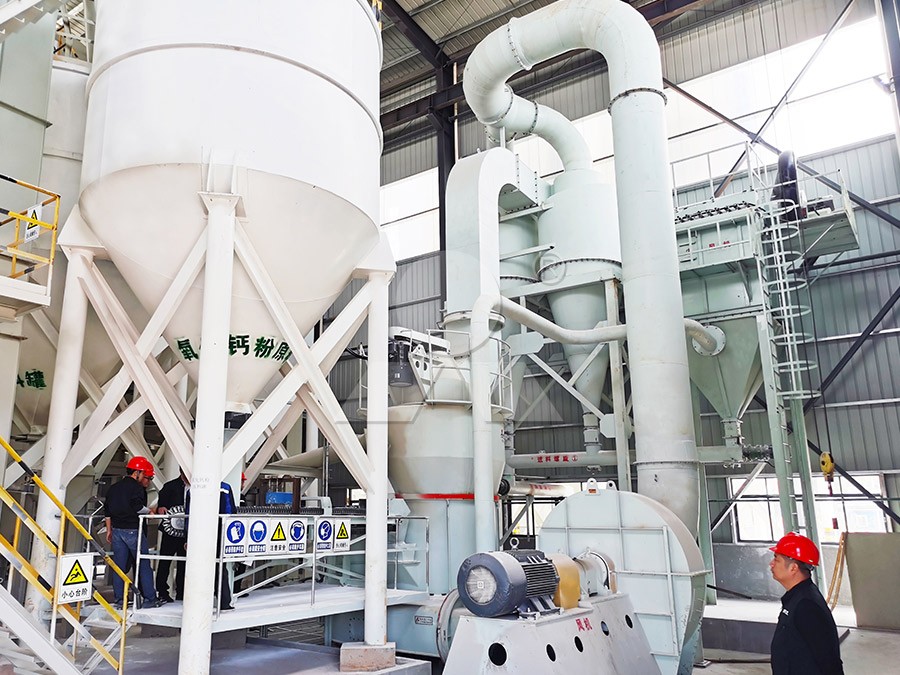
After achieving stable operation at full capacity with the desired product specifications, conduct a formal handover. Key operational best practices include: establishing a routine lubrication schedule, regularly checking wear parts like grinding rolls and rings, and monitoring the pulse dust collector’s differential pressure to ensure timely filter bag cleaning. For large-scale, integrated projects requiring simultaneous drying and grinding of non-metallic minerals or coal, our LM Vertical Grinding Mill series offers unparalleled efficiency. With capacities up to 340 tph, it integrates multiple processes, reduces energy consumption by 30-40%, and features a compact design that cuts floor space by half compared to traditional ball mills.
Remember, consistent preventive maintenance is far more cost-effective than reactive repairs. Keep a log of operational parameters and scheduled inspections to maximize your MTM mill’s service life and return on investment.
Frequently Asked Questions (FAQ)
Q1: What is the recommended interval for checking and replacing the grinding roller and ring?
A: The service life depends entirely on the abrasiveness of the material being processed. As a general guideline, inspect the wear condition after every 500-800 operating hours initially. Based on the observed wear rate, you can establish a predictive maintenance schedule. Always use genuine LIMING wear parts to maintain optimal grinding efficiency and geometry.
Q2: During operation, we notice abnormal vibration. What are the most likely causes?
A: Sudden vibration usually points to an imbalance or misalignment. First, check for uneven feeding or a foreign metal object in the grinding chamber. If clear, stop the mill and inspect: 1) Tightness of all foundation bolts and connecting bolts, 2) Wear condition of grinding rolls (uneven wear causes imbalance), 3) Coupling alignment between motor and reducer, and 4) Balance of the classifier rotor blades.
Q3: How do we adjust the final product fineness?
A: Product fineness is primarily controlled by the speed of the built-in powder separator (classifier). Increasing the rotor speed results in a finer product, while decreasing it produces a coarser powder. Refer to the control panel to adjust the frequency converter governing the classifier motor. Additionally, ensure the blower air volume is correctly set, as airflow assists in material transportation and classification.
Q4: The system negative pressure is unstable. What should we check?
A: Unstable negative pressure often indicates an air leak or a blockage. Systematically inspect all ducting flanges, gaskets, and inspection doors for leaks. Check the pulse dust collector’s filter bags for clogging and ensure the pulse cleaning system is functioning correctly. Also, verify that the discharge valves (rotary airlock) under the cyclones and dust collector are properly sealed and rotating to prevent false air ingress.
Q5: Can the MTM mill handle moist materials?
A: The standard MTM mill is designed for grinding materials with moisture content typically below 6%. For materials with higher moisture, a hot air source (from a furnace or hot air generator) can be connected to the mill’s inlet to provide simultaneous drying and grinding. The system’s airflow and temperature must be calculated based on the moisture evaporation requirement to prevent condensation in the pipelines.