
Iron Ore Ball Mill Installation and Erection Step-by-Step Guide
We provide a wide range of mills — including Raymond mill, trapezoidal mill, vertical mill, ultrafine mill, and ball mill, obtained ISO9001 international quality certification, EU CE certification, and Customs Union CU-TR certification. Suitable for processing minerals such as limestone, phosphate, quicklime, kaolin, talc, barite, bentonite, calcium carbonate, dolomite, coal, gypsum, clay, carbon black, slag, cement raw materials, cement clinker, and more.
The discharge range of these mills can be adjusted to meet specific processing needs, typically from 80-400 mesh, 600-3250 mesh, and can achieve the finest particle size of up to 6000 mesh(D50).
If you are looking for a reliable grinding solution to turn stone or minerals into fine powder, please feel free to contact our online customer service.
Iron Ore Ball Mill Installation and Erection Step-by-Step Guide
Proper installation of your iron ore ball mill is absolutely critical for achieving optimal performance, long service life, and maximized return on investment. This guide outlines the key steps for a successful installation and commissioning process. Remember, safety is paramount—always follow local regulations and manufacturer’s guidlines throughout the project.
Phase 1: Pre-Installation Foundation & Site Preparation
The foundation is the bedrock of your milling operation. A poorly designed or constructed foundation will lead to excessive vibration, misalignment, and premature wear.
- Review Drawings: Thoroughly examine the foundation drawings supplied by the manufacturer. Confirm all dimensions, anchor bolt locations, and load-bearing requirements.
- Concrete Pour: Use high-quality concrete with the specified compressive strength. Ensure the foundation block is massive enough to dampen vibrations and is poured in one continuous operation to avoid weak joints.
- Anchor Bolts: Precisely position and secure the anchor bolt frames. Protect the bolt threads during the concrete pour. Allow the concrete to cure completely for the recommended time (typically 7-28 days) before proceeding.
- Site Access: Ensure there is clear and safe access for crane operation and the delivery of large components like the mill shell, girth gear, and motor.
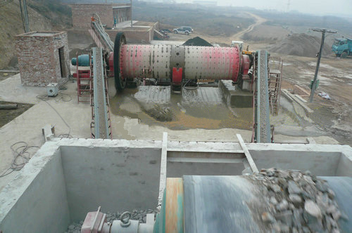
Phase 2: Mechanical Erection of Major Components
This phase involves the careful assembly of the mill’s core mechanical parts. A certified crane and experienced rigging crew are essential.
- Position Main Bearings: Carefully lower the main bearing housings onto the foundation. Use precision leveling instruments to ensure they are perfectly level and aligned with each other. This is a non-negotiable step for preventing future bearing failure.
- Install Mill Shell: Lift and position the mill shell onto the main bearings. Gradually tighten the anchor bolts in a cross-pattern to the specified torque.
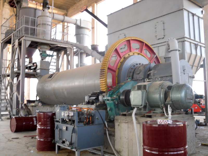
- Mount Girth Gear & Pinion: Install the girth gear onto the mill shell. Then, position the pinion gear and its drive assembly. The alignment between the girth gear and pinion is crucial. Check the gear mesh backlash and contact pattern according to the manual’s specifications.
- Install Liners & Grinding Media: After the mechanical assembly is secure, begin installing the internal liners (lifters, shell plates). Finally, charge the mill with the specified type and quantity of grinding balls.
Phase 3: Electrical, Lubrication, and Auxiliary Systems
A ball mill is more than just a rotating drum. The supporting systems are vital for reliable operation.
- Motor & Drive System: Install and align the main drive motor, reducer, and couplings. Ensure all electrical connections are made by a qualified electrician.
- Lubrication System: Install the high-pressure hydraulic lubrication system for the startup and the continuous low-pressure oil circulation system for the main bearings. Flush the systems thoroughly before connecting them to the bearings.
- Auxiliaries: Install feeders, conveyors, and discharge systems. Connect dust collection equipment to maintain a clean and safe environment.
Phase 4: Commissioning & First Run
Do not simply flip the switch and hope for the best. A methodical commissioning process is required.
- Pre-Start Checks: Verify all guard are in place. Manually rotate the mill to ensure nothing is obstructing movement. Confirm oil is flowing to all bearings.
- Test Run Without Feed (No-Load): Start the lubrication system and run the mill empty for several hours. Monitor bearing temperatures, vibration levels, and sound. Everything should be smooth and quiet.
- Gradual Feed Introduction: Begin feeding ore slowly into the mill. Gradually increase the feed rate to the designed capacity while continously monitoring motor current, bearing temperature, and product output.
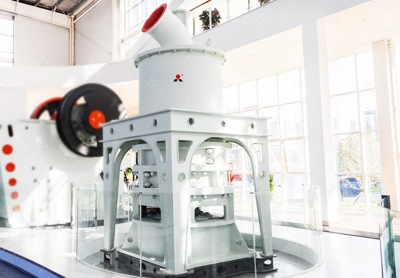
Considering an Upgrade? Modern Alternatives for Fine Grinding
While ball mills are workhorses for iron ore grinding, modern operations often seek higher efficiency for ultra-fine products. For applications requiring a fineness between 325-2500 meshes, our MW Ultrafine Grinding Mill presents a superior alternative.
This advanced mill boasts features that directly adress the limitations of traditional ball mills:
- Higher Yielding, Lower Energy Consumption: Delivers 40% higher capacity than jet mills and uses only 30% of the energy, drastically reducing operating costs.
- Eco-Friendly Design: An integrated efficient pulse dust collector and muffler ensure no dust pollution and low noise operation, meeting strict environmental standards—a significant advantage over open-circuit ball mills.
- Worry-Free Maintenance: A key design advantage is the absence of rolling bearings and screws in the grinding chamber. This eliminates the most common failure points in a ball mill, preventing costly downtime from bearing seizures or loose liner bolts.
For operations looking to optimize their fine grinding circuit, the MW Series offers a compelling combination of performance, efficiency, and reliability.
Conclusion
A meticulous approach to ball mill installation, from foundation prep to gradual commissioning, is the best insurance policy for years of trouble-free operation. Don’t cut corners. For those looking beyond traditional technology, exploring advanced solutions like our MW Ultrafine Grinding Mill can unlock new levels of efficiency and product quality in your iron ore processing flow sheet.