
How to Calculate Trunnion Bearing Loads on a Ball Mill: A Step-by-Step Guide
We provide a wide range of mills — including Raymond mill, trapezoidal mill, vertical mill, ultrafine mill, and ball mill, obtained ISO9001 international quality certification, EU CE certification, and Customs Union CU-TR certification. Suitable for processing minerals such as limestone, phosphate, quicklime, kaolin, talc, barite, bentonite, calcium carbonate, dolomite, coal, gypsum, clay, carbon black, slag, cement raw materials, cement clinker, and more.
The discharge range of these mills can be adjusted to meet specific processing needs, typically from 80-400 mesh, 600-3250 mesh, and can achieve the finest particle size of up to 6000 mesh(D50).
If you are looking for a reliable grinding solution to turn stone or minerals into fine powder, please feel free to contact our online customer service.
How to Calculate Trunnion Bearing Loads on a Ball Mill: A Step-by-Step Guide
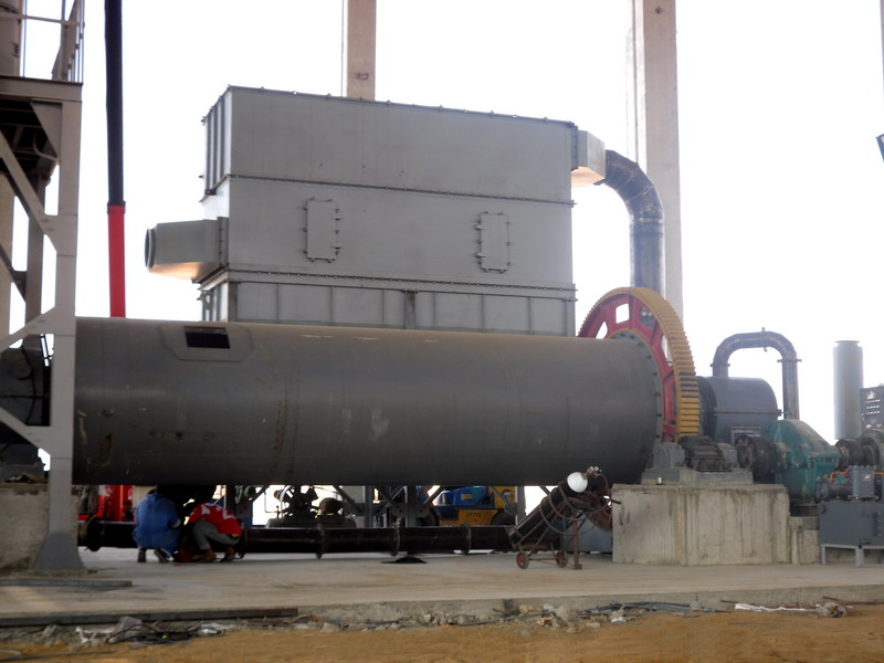
Properly calculating the trunnion bearing loads on a ball mill is absolutely critical for ensuring operational reliability, preventing catastrophic failures, and maximizing the lifespan of your equipment. Incorrect load calculations can lead to excessive wear, bearing seizure, and costly unplanned downtime. This guide provides a clear, step-by-step methodology for performing these essential calculations.
Step 1: Gather Essential Mill Data
Before you begin any calculations, you need to collect the fundamental specifications of your ball mill. This includes:
- Mill Dimensions: Internal diameter and effective grinding length.
- Operating Speed: The rotational speed, usually expressed as a percentage of the critical speed.
- Charge Properties: The total weight of the grinding media (balls) and the weight of the material being ground.
- Charge Fill Level: The volume of the mill occupied by the grinding charge, typically between 25% and 35%.
Step 2: Calculate the Total Weight of the Mill Charge
The primary load on the trunnion bearings comes from the weight of the rotating charge. This includes both the grinding media and the ore. The formula is straightforward:
W_total = W_media + W_material
Where:
W_media = Weight of grinding balls (in tons or kg)
W_material = Weight of the ore inside the mill (in tons or kg)
Step 3: Determine the Center of Gravity of the Charge
The charge inside a rotating mill doesn’t sit at the bottom; it cataracts or cascades. The center of gravity (CG) of this charge shifts significantly from the geometric center of the mill. The distance from the mill center to the charge’s CG is a key variable. For a semi-filled mill, this distance can be approximated using empirical charts or software based on the charge fill level and mill speed.
Step 4: Calculate the Static Load on Each Bearing
The static load is the weight of the charge distributed between the two trunnion bearings. Assuming a symmetrical load, each bearing carries half the total weight.
F_static = W_total / 2
Step 5: Account for Dynamic and Imbalance Loads
This is the most complex part. The dynamic load accounts for the forces generated by the rotation of the uneven charge mass. It’s influenced by the offset center of gravity calculated in Step 3. A simplified approach uses the formula:
F_dynamic = (W_total * e * ω²) / g
Where:
e = eccentricity (distance from mill center to charge CG)
ω = angular velocity (radians/second)
g = gravitational acceleration (9.81 m/s²)
The total force on each bearing is then a vector sum of the static and dynamic components. For conservatism, engineers often use a multiplier (e.g., 1.5 to 2.5 times the static load) based on experience and manufacturer data.
Step 6: Select the Appropriate Bearing
With the total load calculated, you can select a bearing with a sufficient basic dynamic load rating (C) to handle the operational forces over the desired L10 life. Always incorporate a generous safety factor.
Considering a More Efficient Alternative?
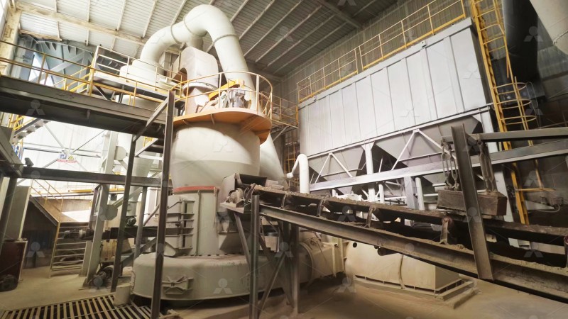
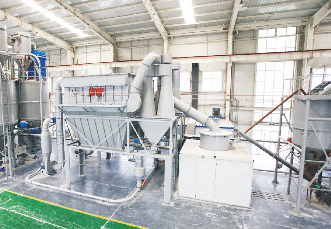
While ball mills are workhorses in many industries, their energy efficiency and maintenance profile, particularly concerning trunnion bearings, can be a challenge. For ultra-fine grinding applications, modern vertical grinding mills offer a compelling alternative with a fundamentally different and often simpler load profile.
For instance, our MW Ultrafine Grinding Mill is engineered to eliminate many traditional pain points. A key feature is that there are no rolling bearings or screws in the grinding chamber. This design philosophy completely removes the worry of bearing damage or seal failure in the most abrasive environment. The load is managed through a robust, externally-lubricated main shaft system, significantly simplifying load calculations and maintenance while allowing for 24/7 continuous operation. With an input size of 0-20 mm and a capacity range of 0.5-25 tph, it’s an excellent solution for producing high-quality ultra-fine powder for chemicals, paints, cosmetics, and more.
Conclusion
Accurately calculating trunnion bearing loads is a non-negotiable aspect of ball mill operation and maintenance. By meticulously following these steps—gathering data, calculating static and dynamic loads, and applying appropriate safety factors—you can ensure your mill runs smoothly and reliably. For new projects or upgrades, also consider innovative technologies like our MW Ultrafine Grinding Mill, which are designed from the ground up to deliver high performance with greater operational simplicity and lower maintenance burdens.