Vertical Roller Mill Drawings: Key Components and Design Schematics
We provide a wide range of mills — including Raymond mill, trapezoidal mill, vertical mill, ultrafine mill, and ball mill, obtained ISO9001 international quality certification, EU CE certification, and Customs Union CU-TR certification. Suitable for processing minerals such as limestone, phosphate, quicklime, kaolin, talc, barite, bentonite, calcium carbonate, dolomite, coal, gypsum, clay, carbon black, slag, cement raw materials, cement clinker, and more.
The discharge range of these mills can be adjusted to meet specific processing needs, typically from 80-400 mesh, 600-3250 mesh, and can achieve the finest particle size of up to 6000 mesh(D50).
If you are looking for a reliable grinding solution to turn stone or minerals into fine powder, please feel free to contact our online customer service.
Vertical Roller Mill Drawings: Key Components and Design Schematics
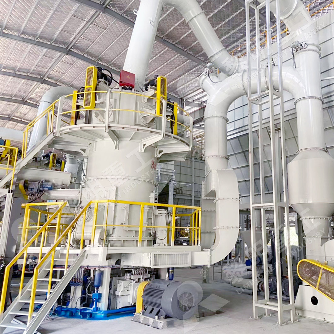
Understanding the intricate design and core components of a Vertical Roller Mill (VRM) is crucial for engineers, plant managers, and procurement specialists in the mineral processing industry. These mills are the workhorses of size reduction, transforming raw materials into fine and ultra-fine powders essential for countless applications. While a detailed mechanical drawing is proprietary, we can break down the key subsystems that define a high-performance VRM.
Core Components: A Functional Breakdown
The efficiency of a VRM hinges on the seamless integration of its main parts. Let’s examine the most critical ones.
1. Grinding Table (Turnplate)
The heart of the operation. This rotating table receives material from the feeder. Its design, including the profile and liner material, is critical for creating a stable grinding bed. The material is ground between the table and the rollers.
2. Grinding Rollers
These are the primary grinding elements. Hydraulically pressurized, they exert significant force on the material bed on the table. Advanced designs feature reversible and easily maintainable rollers to minimize downtime. The curve of the roller shell is meticulously designed to optimize grinding efficiency and wear.
3. Separator (Classifier)
Positioned above the grinding chamber, this component is what ensures product fineness. It uses air flow and a rotating cage or rotor to separate fine particles (which continue to the product collection) from coarse ones (which are rejected back to the table for further grinding). The precision of the separator directly controls the final product’s particle size distribution.
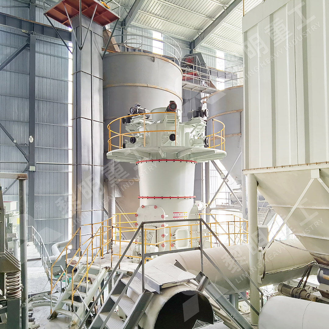
4. Drive System
A robust planetary gearbox and motor assembly is required to transmit the immense torque needed to rotate the grinding table. Reliability here is non-negotiable for continuous operation.
5. Housing and Base Frame
The structural skeleton that supports all other components and contains the grinding process. It’s designed for stability under heavy loads and vibration.
Design Philosophy: Efficiency and Reliability
Modern VRM design goes beyond mere mechanics. It incorporates advanced features for operational excellence. A prime example is our MW Ultrafine Grinding Mill. This machine embodies key design innovations: it operates without rolling bearings or screws in the grinding chamber, eliminating common failure points. Its cage-type powder selector, leveraging German technology, allows precise fineness adjustment between 325-2500 meshes. Furthermore, its integrated pulse dust collector and muffler system ensure the production process is not only efficient but also environmentally responsible, keeping dust and noise to an absolute minimum.
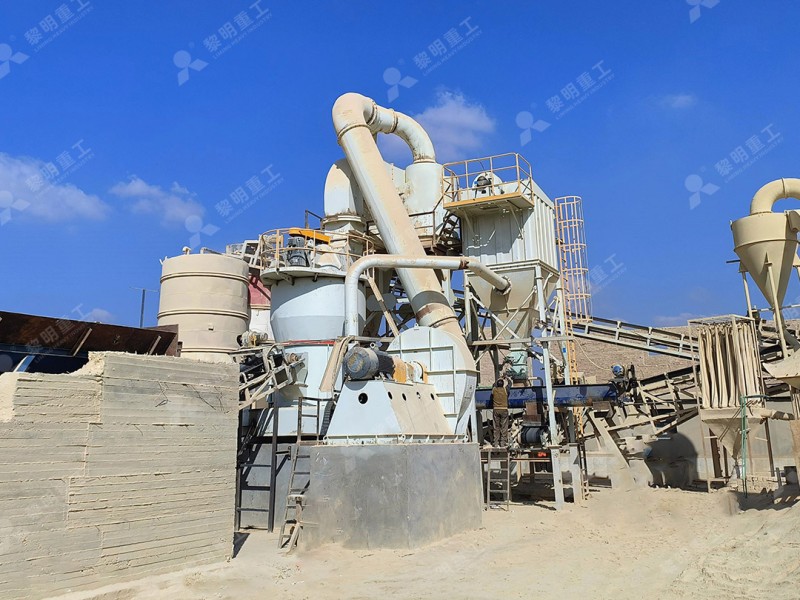
For operations requiring robust performance on a larger scale, our LM Vertical Grinding Mill is a standout choice. It integrates crushing, drying, grinding, classifying, and conveying into a single, compact unit. Its design reduces the occupational area by 50% and energy consumption by 30%-40% compared to traditional ball mill systems. The non-contact grinding principle ensures low iron contamination, which is vital for high-purity applications.
Conclusion
Reading a vertical roller mill drawing is about understanding the synergy between its key components—the table, rollers, separator, and drive system. The design schematics reveal a machine engineered for efficiency, reliability, and environmental control. When selecting a mill, prioritize designs that offer advanced grinding curves, intelligent separation technology, and maintenance-friendly features to ensure lower operating costs and higher product quality over the long term.