
MTW Series European Type Grinding Mill Installation Requirements and Guidelines
We provide a wide range of mills — including Raymond mill, trapezoidal mill, vertical mill, ultrafine mill, and ball mill, obtained ISO9001 international quality certification, EU CE certification, and Customs Union CU-TR certification. Suitable for processing minerals such as limestone, phosphate, quicklime, kaolin, talc, barite, bentonite, calcium carbonate, dolomite, coal, gypsum, clay, carbon black, slag, cement raw materials, cement clinker, and more.
The discharge range of these mills can be adjusted to meet specific processing needs, typically from 80-400 mesh, 600-3250 mesh, and can achieve the finest particle size of up to 6000 mesh(D50).
If you are looking for a reliable grinding solution to turn stone or minerals into fine powder, please feel free to contact our online customer service.
MTW Series European Type Grinding Mill Installation Requirements and Guidelines
Proper installation is the cornerstone of achieving optimal performance, longevity, and safety for any industrial grinding system. The MTW Series European Type Grinding Mill, renowned for its advanced design and robust construction, demands meticulous attention during its setup phase. This guide outlines the critical requirements and step-by-step procedures to ensure a flawless installation, laying the groundwork for years of efficient and trouble-free operation.
Pre-Installation Planning and Foundation Preparation
Before the mill arrives on site, comprehensive planning is essential. Begin by thoroughly reviewing the foundation drawings and general layout provided by our engineering team. The foundation must be constructed from high-strength reinforced concrete, capable of supporting at least 2.5 times the total weight of the mill and its ancillary equipment. It is crucial to isolate the mill’s foundation from the building’s structural framework to prevent vibration transmission.
Allow the foundation to cure completely for a minimum of 28 days, ensuring it is level, clean, and free of debris. Precisely position and secure the anchor bolts within wooden boxes or sleeves before pouring the concrete, verifying their alignment and projection height against the drawings. A well-prepared foundation prevents misalignment, reduces stress on the machine frame, and is non-negotiable for operational stability.
Uncrating, Handling, and Major Component Assembly
Upon delivery, inspect all crates for signs of damage during transit. Use appropriate lifting equipment, such as cranes or forklifts with adequate capacity, and always lift from the designated lifting lugs on the main frame and components. Never lift the mill using the motor, reducer, or any piping.
The assembly typically follows this sequence:
- Base Frame and Reducer: Carefully lower the main base frame onto the foundation pads. Install the reducer onto its base, ensuring perfect alignment with the motor shaft using dial indicators. This step is critical; improper alignment will cause premature wear, vibration, and potential failure.
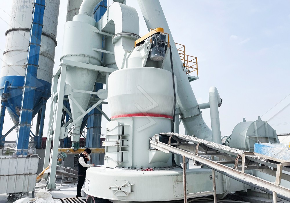
- Grinding Roller and Ring Assembly: Install the grinding ring on the turnplate. Then, mount the grinding roller assembly onto the rocker arm. The unique design of MTW mills, such as the MTW European Trapezium Grinding Mill, features wear-resistant alloy rollers and a cambered air duct for smooth feeding and lower energy consumption. Pay close attention to the clearance between the roller and the ring during initial setup.
- Classifier Installation: Mount the powder separator (classifier) atop the mill housing. For models featuring advanced separation technology like the cage-type selector, handle the internal rotor vanes with extreme care to avoid deformation.
Ancillary System Integration: Air, Feed, and Dust Control
The mill does not operate in isolation. Seamless integration of supporting systems is vital.
- Feeding System: Connect the vibrating feeder or screw conveyor to the mill’s inlet. Ensure the feed rate is adjustable and can be synchronized with the mill’s power consumption for optimal control.
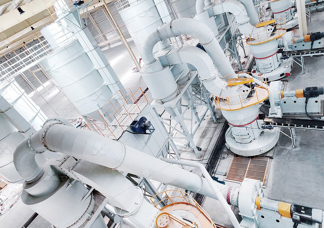
- Air System: Connect the air ducting between the mill outlet, cyclone collector, bag filter, and the induced draft fan. All connections must be airtight to maintain the necessary negative pressure within the grinding chamber. For ultra-fine applications requiring superior classification, consider integrating a system with our MW Ultrafine Grinding Mill, which boasts a highly precise cage-type powder selector adjustable between 325-2500 meshes, achieving a remarkable d97≤5μm in a single pass.
- Dust Collection: Install the pulse-jet baghouse or other dust collector as per the system design. Connect the clean air return duct to the fan inlet if applicable. This closed-loop system is key to the MTW series’ eco-friendly operation, ensuring no dust pollution.
- Electrical and Lubrication: Route power and control cables to the main motor, fan motor, feeder, and control cabinet. Fill the reducer and central lubrication system (if equipped) with the recommended grade and quantity of oil. The MTW-Z model’s innovative dilute oil lubrication for grinding rollers is a standout feature, offering maintenance-free operation compared to traditional grease systems.
Alignment, Final Checks, and Commissioning
Once all components are in place, perform a final comprehensive alignment check. Verify the concentricity and verticality of the main shaft. Manually rotate the grinding roller assembly to ensure it moves freely without striking the ring.
Before the first start-up, conduct these essential checks:
- Confirm all electrical connections are tight and correct.
- Verify the rotation direction of the main motor, fan, and classifier motor.
- Ensure all safety guards are securely installed.
- Check that all lubrication points are serviced.
- Clear the area of tools and personnel.
Begin commissioning with an empty mill run. Start the system in sequence: dust collector → fan → classifier → main mill motor → feeder. Monitor amperage, vibration, and unusual noise for at least 2-4 hours. Only after a successful no-load test should you begin feeding material, starting with a low feed rate and gradually increasing to the design capacity while monitoring all parameters.
Conclusion
Adhering to these installation guidelines is not merely a procedural task; it is an investment in the future reliability and productivity of your grinding operation. The MTW Series European Type Grinding Mill, with its intelligent design features like the split-type shovel blade and elastic volute damping structure, is engineered for excellence. A precise and careful installation unlocks its full potential, ensuring higher yielding rates, lower energy consumption, and the worry-free operation that defines our equipment. Always refer to the specific manual for your model and consult with our technical service team for support.
Frequently Asked Questions (FAQ)
- What is the recommended clearance for the grinding roller and ring during initial installation?
The initial clearance is typically set by the manufacturer and indicated in the installation manual. It is usually in the range of 5-10 mm and will self-adjust as material is fed and the hydraulic system takes effect. Never set the rollers to contact the ring directly during installation. - How critical is the alignment between the motor and the reducer?
It is absolutely critical. Misalignment is a leading cause of vibration, excessive bearing wear, and coupling failure. Laser or dial indicator alignment must be performed to within the tolerances specified in the manual (often less than 0.05mm). - Can the MTW mill process moist materials?
The standard MTW mill is designed for grinding dry materials. If your raw material has high moisture content, a separate drying system (like a paddle dryer) must be installed upstream, or you should consider our LM Vertical Grinding Mill, which integrates crushing, drying, and grinding for moist materials like slag and coal. - What is the purpose of the negative pressure in the grinding chamber?
Maintaining a slight negative pressure prevents dust from escaping at seals and connections, ensuring a clean working environment. It also facilitates the smooth flow of the air-powder mixture through the system to the collector. - How often should the grinding rollers and rings be inspected?
Perform a visual inspection through the access doors during routine monthly maintenance. The actual wear life depends on the material abrasiveness. The wear-resistant alloy used in MTW mills significantly extends service life, but planning for inspection during annual shutdowns is a best practice. - Why is there no load on the main motor during the empty run test?
The empty run test verifies mechanical integrity—bearing temperature, gear meshing, absence of scraping sounds—without the variable of grinding load. It ensures the machine is mechanically sound before applying the stress of grinding, which would mask or exacerbate initial installation flaws.