
The Schematic Sketch of Roller Mills Circuit: A Comprehensive Guide for Industrial Grinding Operations
We provide a wide range of mills — including Raymond mill, trapezoidal mill, vertical mill, ultrafine mill, and ball mill, obtained ISO9001 international quality certification, EU CE certification, and Customs Union CU-TR certification. Suitable for processing minerals such as limestone, phosphate, quicklime, kaolin, talc, barite, bentonite, calcium carbonate, dolomite, coal, gypsum, clay, carbon black, slag, cement raw materials, cement clinker, and more.
The discharge range of these mills can be adjusted to meet specific processing needs, typically from 80-400 mesh, 600-3250 mesh, and can achieve the finest particle size of up to 6000 mesh(D50).
If you are looking for a reliable grinding solution to turn stone or minerals into fine powder, please feel free to contact our online customer service.
The Schematic Sketch of Roller Mills Circuit: A Comprehensive Guide for Industrial Grinding Operations
The schematic sketch of a roller mills circuit is a fundamental blueprint for any industrial grinding operation. It visually represents the flow of materials and the intricate arrangement of machinery components, serving as a critical tool for engineers and plant operators. Understanding this diagram is paramount for optimizing efficiency, ensuring consistent product quality, and minimizing operational costs in industries ranging from mining and cement production to chemical processing.
Deciphering the Key Components
A typical roller mill circuit schematic is more than just lines and boxes; it’s a map of a complex process. Let’s break down the core components you’ll encounter:
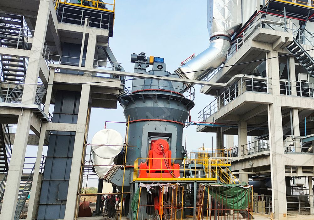
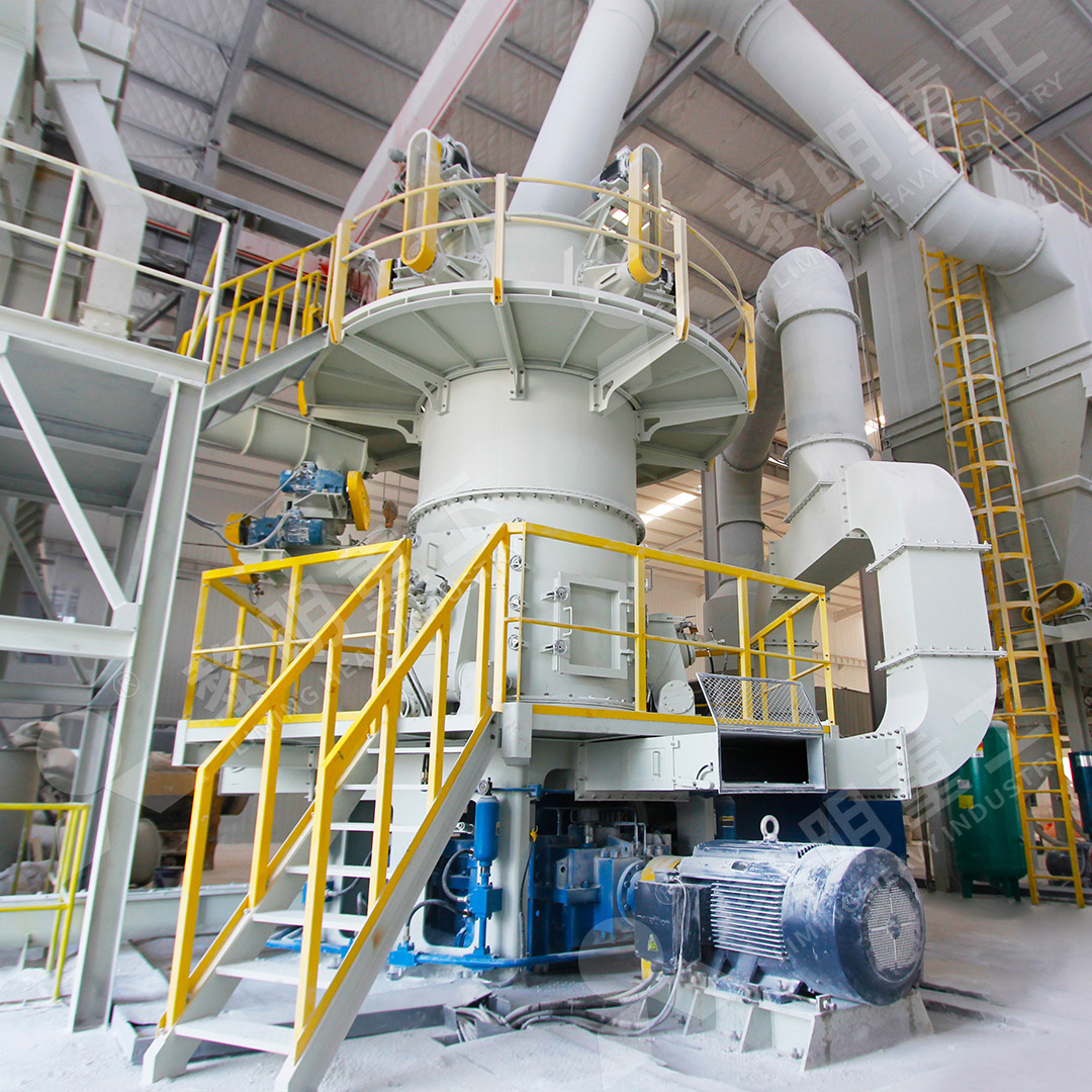
- The Roller Mill: The heart of the operation. This is where size reduction happens. Material is fed between rotating rollers and a static grinding ring or table, being crushed and ground into finer particles.
- The Classifier (or Separator): This crucial component acts as a quality control gate. It uses air flow and internal mechanisms (like rotating rotors or cages) to separate fine, product-sized particles from coarse ones that need further grinding.
- The Cyclone Separator: Working on centrifugal principles, this unit separates the bulk of the fine powder from the transporting air stream. The powder collects at the bottom for discharge, while the air moves on.
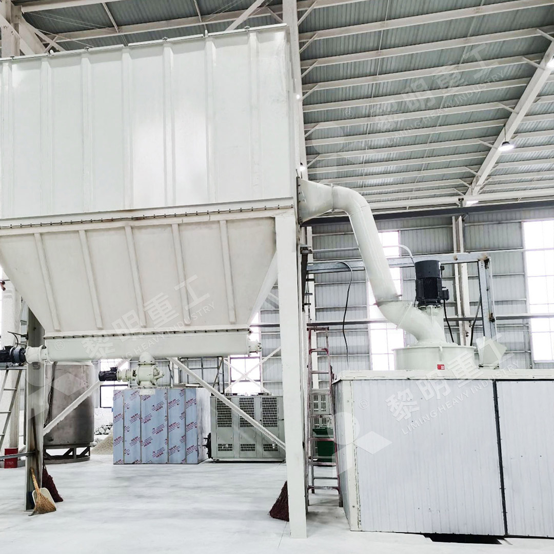
- The Dust Collector: Often a baghouse or pulse-jet filter, this is the environmental guardian of the system. It captures any remaining fine dust from the air stream before it’s exhausted, ensuring clean operation and protecting the environment.
- Feeders, Elevators, and Ductwork: These are the arteries and veins, constantly moving material and air throughout the closed-circuit system.
The Flow of Materials: A Step-by-Step Journey
Following the schematic reveals the material’s journey:
- Raw material (crushed to a suitable size, e.g., 0-20mm) is fed into the roller mill.
- Inside the mill, it is repeatedly ground between the rollers and the grinding surface.
- A stream of air carries the ground powder upwards out of the mill and into the classifier.
- The classifier performs its sorting magic. Coarse particles are rejected and fall back down into the mill for regrinding.
- The fine, accepted powder-laden air travels to the cyclone separator, where most of the product is recovered.
- The now partially cleaned air proceeds to the dust collector for final filtration before being released or recirculated.
- The final product is collected from the discharges of the cyclone and the dust collector.
Optimizing Your Grinding Circuit
Understanding the schematic allows for precise optimization. Key levers include adjusting the classifier speed to control product fineness, managing air volume for efficient transport, and monitoring grinding pressure for optimal energy use. A well-balanced circuit maximizes yield while minimizing wear and power consumption.
Choosing the Right Mill for Your Schematic
The choice of roller mill is the most critical decision in designing an efficient circuit. For operations requiring ultra-fine powders with superior efficiency, the MW Ultrafine Grinding Mill is an exceptional choice. This advanced mill is engineered for customers needing to produce high-quality ultra-fine powder between 325-2500 meshes. With an input size of 0-20 mm and a capacity range of 0.5-25 tph, it’s incredibly versatile. Its design boasts higher yielding and lower energy consumption—achieving 40% higher capacity than jet mills while using only 30% of the energy. A significant advantage is its lack of rolling bearings and screws in the grinding chamber, eliminating common failure points and enabling worry-free, continuous 24/7 operation. Coupled with an efficient pulse dust collector, it ensures an eco-friendly process with minimal dust and noise pollution, making it perfect for sensitive applications in chemicals, cosmetics, and food additives.
For another robust solution, particularly for slag or coal, our LM Vertical Grinding Mill integrates crushing, drying, grinding, and classifying into a single, compact unit, reducing the footprint by 50% and energy use by 30-40% compared to traditional ball mills.
In conclusion, mastering the schematic sketch of your roller mill circuit is not just academic; it’s a practical necessity for achieving peak operational performance. By selecting advanced, efficient equipment like our MW Ultrafine Grinding Mill, you can build a circuit that delivers exceptional product quality, reliability, and sustainability.